
Ra0.4 Lathe FactoryMechanical Spindle Cnc Turned Components
Ra0.4 Lathe FactoryMechanical Spindle Cnc Turned Components Description
| Cnc Machining Or Not: | CNC Machining | Material: | Steel/stainless Steel/aluminum/brass |
|---|---|---|---|
| Surface Treatment: | Painting/powder Coating/plating/anodized | Process: | Milling,cnc Machining |
| Product Name: | Customized OEM Custom Steel Cnc Precision Milling Jig Fixture | Drawing Format: | IGS,PDF/IGS/STP/ Etc, |
| High Light: | sus304 lathe machining thread products, 0.03mm tolerance cnc machining metal parts | ||
custom china Mechanical Parts Spindle CNC Turning Parts Lathe Machining Thread Products Durable
Product Details:
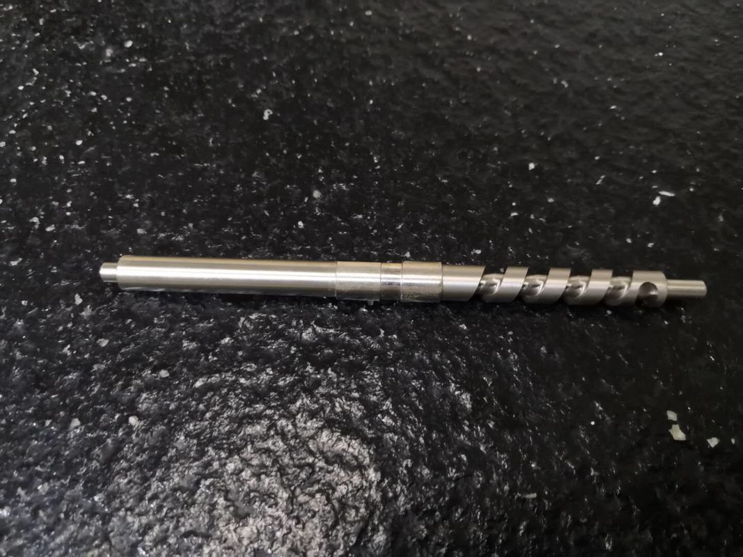
High-quality Lathe machining Thread SUS304products parts CNC Turning Machinery Spares Lathe Factory
Material:SUS304 Rugosity:Ra0.4 Tolerance:0.01-0.03mmDiameter:Ø15mm Conical spiral teeth L*W*H(mm)=15mm*15mm*155mm
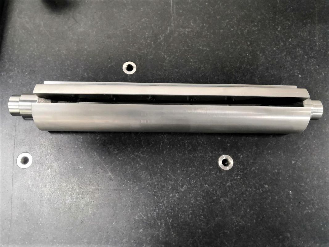
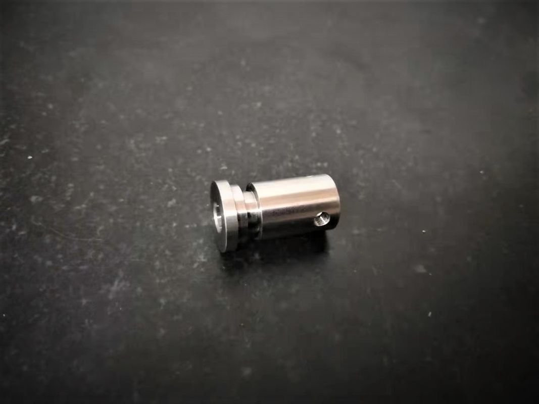
Main Products Display
Metal:Aluminum2024,2A12,5052,6020,6061,6063,7075,45#,SKD11,DC53,SUS304,SUS136.Machine:CNC lathe,Centering Machine,Multi-Axis turning,Purpose:Semiconductor Machinery,Laser Cutting Equipment,Communication equipment,
Testing equipment,Medical equipment,agricultural machinery,electrical appliances products,
Generator parts,Bathroom Parts,Ship accessories,Electric Tool Parts,Monitoring equipment,
what is CNC?
The Basics Of CNC Machining
CNC (Computer Numerical Controlled) machining is a means to remove material with high precision
machines, using a wide variety of cutting tools to create the final design. Common CNC machines
include vertical milling machines, horizontal milling machines, lathes, and routers.
How CNC Machining Works
To successfully make a part on a CNC machine, skilled machinists create programmed instructions using
CAM (Computer Aided Manufacturing) software in conjunction with the CAD (Computer Aided Design)
model provided by the customer. The CAD model is loaded into the CAM software and tool paths are
created based on the required geometry of the manufactured part. Once the tool paths are determined,
the CAM software creates G-Code (machine code) that tells the machine how fast to move, how fast to
turn the stock and/or tool, and where to move the tool or workpiece in a 5-axis X, Y, Z, A, and B
coordinate system.
Products categories
-
Customized SUS304 Lathe Machining Thread CNC Tu...
-

Conical Shaft Lathe Precision Brass Turned Part...
-
Printer Shaft CNC Turning Parts Knob Music Moto...
-

Anodizing CNC Turning Parts For Rechargeable Ba...
-

High Precision Custom Cnc Lathe Machine Parts T...
-

SUS304 CNC Turning Parts Lathe Machining Thread...